Quick Links:
- Home Page
- Game Parts & Supplies
- Games for Sale
- Ordering Info
- Technical Articles
- Game Service & Repair
- Contact Us
|
|
 Bally Short Backbox Games (1982-1983) Bally Short Backbox Games (1982-1983)
This article covers the following Bally models only: Centaur II, Eight Ball Deluxe Limited Edition, Mr. & Mrs. Pac-Man, Rapid-Fire
NOTE: These instructions assume your game has been packaged for shipment as shown in images below. This information is intended to help you set up your pinball machine after it has been shipped to you from our shop. Use this information at your own risk. We (Action Pinball) are not responsible for any damage to you, your location, or your game, that may result from following, or not following the instructions below.
Materials Needed:
- One or two friends to help.
- Scissors or knife.
- 5/8" and 9/16" open-end wrench, or socket wrench.
- Phillips head screwdriver.
 Click on any image below for a larger view. Click on any image below for a larger view.
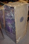 |
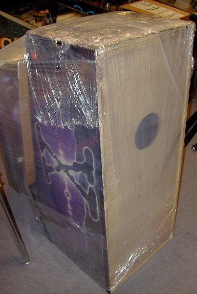
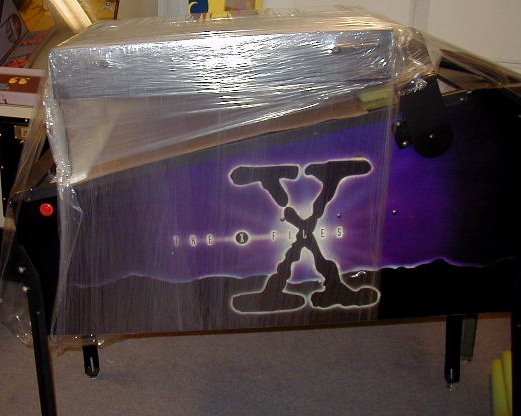
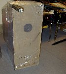
Step 1:Unpack your game to the extent shown in the image to the left. Backbox should still be secured to the main cabinet with stretch-wrap (as shown in image).
USE CAUTION when cutting away any cardboard or stretch-wrap from the game, so as not to cut through the packaging and damage the cabinet surface. Patience and neatness count in this process.
Locate the hardware (bolts, balls, keys, etc) that are packed with the game, and set aside for use during assembly. With backbox still secured to main cabinet (in its "down" position), position the game so that it is sitting on it's back end, coin door facing up, as shown in the image at left. |
 |
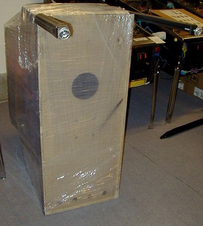
Step 2:
Install front legs:
Locate the 2 front legs. These are the legs with the leg levelers (feet) that are screwed all the way in. (Back legs will have the leg levelers screwed OUT an inch or two- so that the game sits higher in the back, than in the front. Back legs will be installed in Step 4 below).
Locate the 8 leg bolts. Each leg will use 2 leg bolts.
Locate the 8 nylon washers. These will be installed over each of the leg bolts. They help protect the paint finish on the legs when bolts are installed and tightened.
Peel back any plastic stretch wrap covering the leg mounting areas on the front corners of the machine (either side of the coin door).
Align one leg and it's bolt holes with the bolt holes on one front corner of the cabinet. Place 2 leg bolts with nylon washers through the bolt holes of the leg, and down into the holes in the cabinet where they will thread in.
Start each bolt by hand, and ensure that it turns freely as it screws down into the threaded leg bolt plate on the inside of the cabinet. Support the weight of the leg while you start each bolt to ensure the bolt goes in straight, and does not get cross-threaded.
Depending on the game, the leg bolts will require either a 9/16 or 5/8 inch wrench to tighten them. Tighten the bolts so that they are snug, but do not overtighten- we recommend "wrist tight", which is as tight as you can comfortably turn a wrench using only your wrist.
IMPORTANT NOTES ON INSTALLING LEG BOLTS:
- Do not let the weight of the machine rest on the leg & leg bolts as you are installing/tightening the bolts. This can cause the leg bolts and/or leg bolt plate inside the game to strip, which can require a costly repair. Support the weight of the game, and the leg itself, separately, while you are installing the bolts. They should turn freely by hand as you are installing them. Do not force leg bolts.
- Legs need to be snug, but do not need to be overtightened- it is easy to strip the bolts or threads inside the cabinet that hold the bolts, which can require costly repair.
- It's a good idea to make sure the leg bolts are still snug after the game has been in use for a day or two, after everything has settled in. Loose leg bolts can do as much damage as over-tightened leg bolts, so check leg bolts periodically to make sure they are secure.
- The game should never wobble on it's legs, and legs should never move independently of the cabinet. If so, leg bolts may be loose or damaged. Remedy the problem before using the game.
|
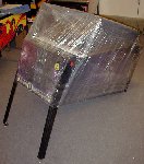 |
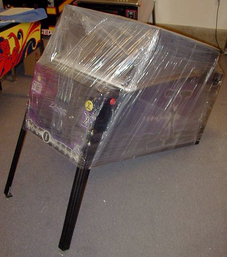
Step 3:
With the front legs installed snugly, lower the front of the machine to the ground, so that the front is sitting on the legs you just installed.
|
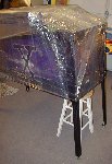 |
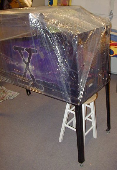
Step 4:
Install back legs:
With 1 or 2 helpers, lift the back end of the machine up off the floor, and have helpers hold it, or place it's back end on a 24-inch stool, as shown in image.
Using the remaining 4 leg bolts and nylon washers, attach the back legs just as you did the front legs. Make sure the weight of the game does not rest on the legs and leg bolts as you are installing them, and do not over-tighten the bolts.
Lift the game up to remove the stool, and then set the back of the game down on it's back legs.
|
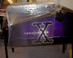 |
Step 5:
Using scissors or a knife, carefully cut away and remove any packing material holding the backbox down (stretch-wrap and/or strap). Be very careful not to cut or scrape/scratch the game when cutting away the packing material. |
|
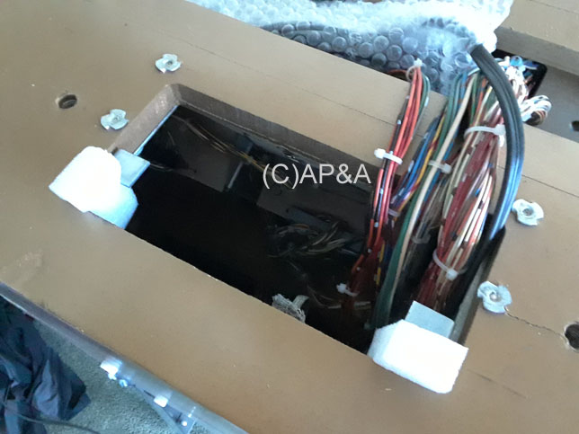
Step 6:
Remove shipping materials and main power cord:
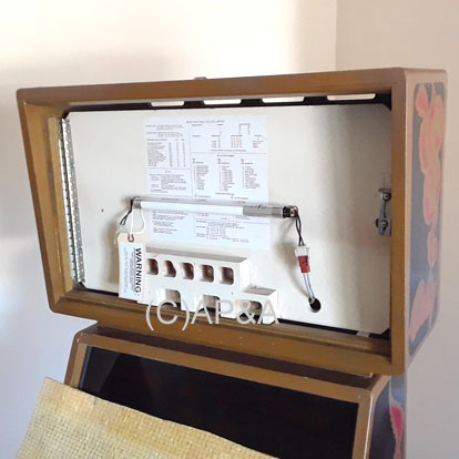
1st Image:
In the top opening at the back of the game's main cabinet where all the wires and cables go, locate and remove the 2 foam pieces holding the metal latches in place for the score display cover.
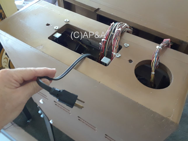
2nd Image:
Locate the main power cord with plug end through the top opening. Pull this cord out and free.
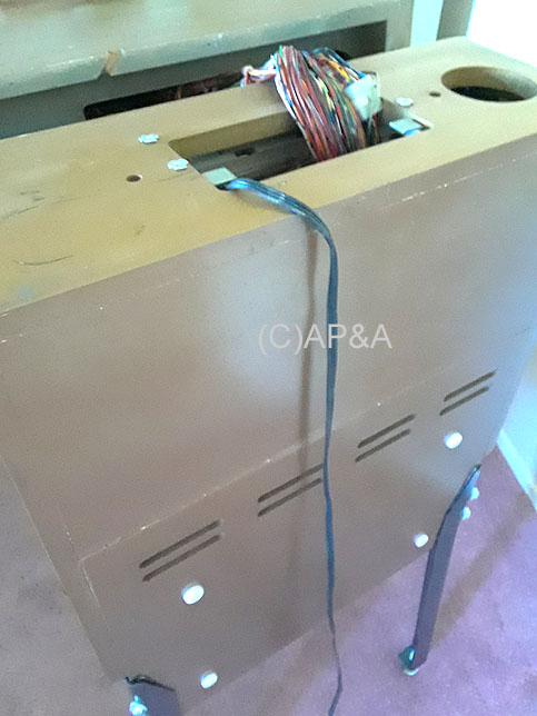
3rd Image:
Droop the power cord over the back edge of the cabinet as shown. Cord must be set here before raising and securing the backbox, otherwise you won't be able to plug the game in.
Use caution- do not yank or pull the cord if it won't come freely. Doing so may damage other wiring or parts inside the game. If the cord seems to be stuck, try to free it by jiggling the cord, reaching inside the cabinet if possible, or otherwise untangling it from other wires/cables in this area.
|
|
Step 7:
Raise backbox into position:
Be sure all wrapping/packaging has been removed from the top of the backbox so that it is free, as it rests face down over the playfield portion of the main cabinet.
Using a helper, carefully lift the backbox up and onto the back of the main cabinet for proper mounting. Feed wiring/cables down into the main cabinet as you go, being careful not to pinch any between the main cabinet and backbox.
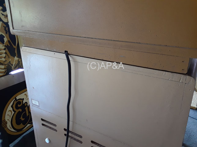
Route the power cord through the cut-out groove at the lower back of the backbox so that it is not pinched when the backbox is resting on the main cabinet.
Center the backbox as best you can- from left to right- over the main cabinet. Align the back of the backbox with the back of the main cabinet as shown in the image.
Have your helper securely hold the backbox in the upright position and proceed to the next step.
|
|
Step 8:
Backglass removal for backbox bolt installation:
IMPORTANT: Have a helper securely hold the backbox in the upright position while you complete this, and the next step. This will prevent the backbox from falling over or off of the game which can cause major damage or injury.
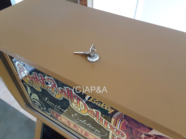
1st Image:
Locate the game keys and unlock the backbox. Backbox lock is located on the top center of the backbox. A 1/4 turn of the lock will unlock the backglass and allow it to be removed.
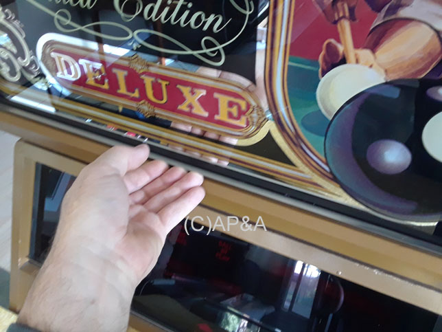
2nd Image:
With backbox unlocked, use the metal lift channel at the bottom of the backglass to lift the backglass up, as it sits in the backbox frame. With the backbox properly unlocked, the backglass should lift up about 1/2 inch, and clear the bottom of the backbox frame.
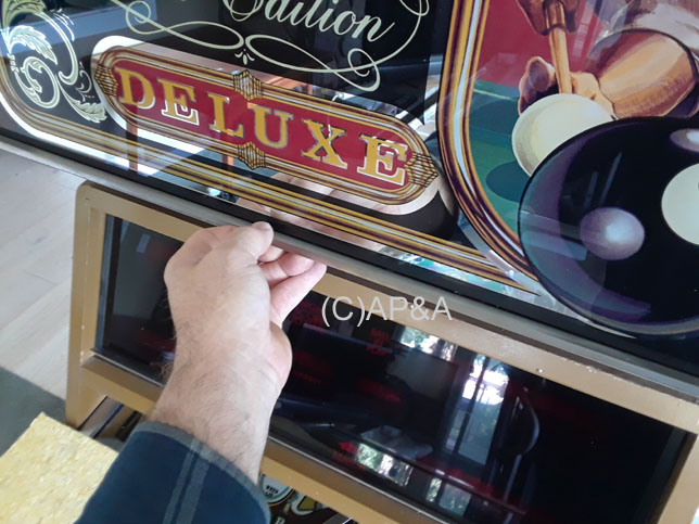
3rd Image:
With backglass lifted up, gently pull the bottom of the backglass out, towards the front, about 1-2 inches- enough to clear the backbox frame.
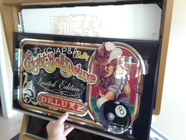
4th Image:
Gently lower the backglass down until it clears the top of the backbox frame, and is free. The whole backglass can now be lifted away and set carefully aside to gain access into the backbox.
NOTE: Always use great care when handling the backglass on any pinball machine. Backglasses are very fragile and can be broken very easily. Replacement backglasses can also be very expensive, and difficult, if not impossible, to locate. Always use caution!
|
|
Step 9:
Backbox bolt installation:
IMPORTANT: Have a helper continue to securely hold the backbox in the upright position while you complete this step. This will prevent the backbox from falling over or off of the game which can cause major damage or injury.
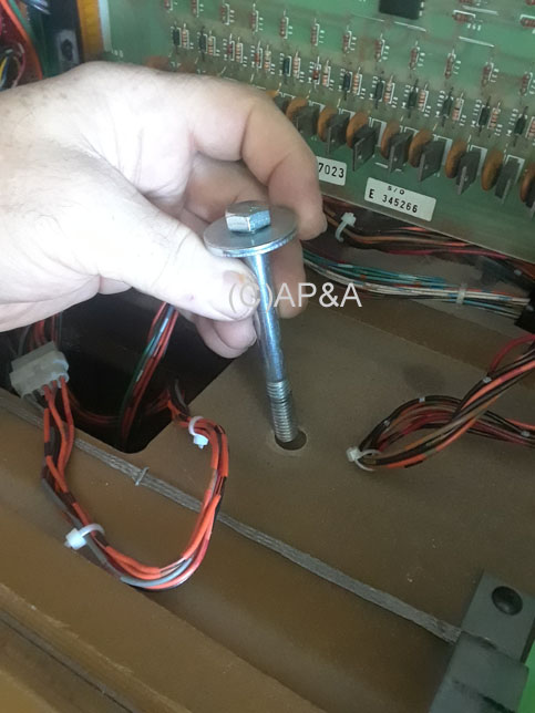
Locate the 2 long backbox bolts with metal washers, included in your game's parts/accessories, and have them ready for installation. See image # 4 at left for identification of the bolts/washers used in this step.
1st Image:
Locate the insert door panel behind the backglass. Depending on the game you have, this panel will either be made of wood, or metal.
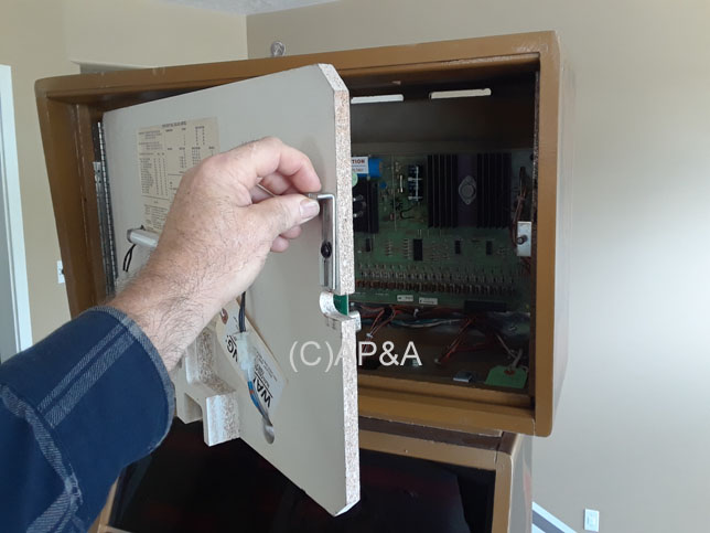
2nd Image:
For wood panels, locate the latch on the right side that secures the insert door panel. You will need to lift the latch to allow the panel to be opened. (If your game was shipped to you, there may be a shipping screw and tag that need to be removed from the latch first, before it can be opened.)
For metal panels (not pictured), locate the Phillips-head screw on the right side that secures the door. You will need to remove the screw to allow the panel to be opened.
3rd Image:
Open the insert panel door, which will swing out to the left, to allow you access to the inside of the backbox.
4th Image:
Drop the 2 long bolts with metal washers into the 2 bolt holes on the bottom panel of the backbox interior (right side pictured- left side similar).
You may need to wiggle each bolt around a bit in order to find the threads under the backbox that the bolts will screw into. Make sure the bolts are going STRAIGHT into the threads with ease, and not leaning to one side, or being stubborn or difficult to turn. If the bolts are leaning to the left/right, or forward/backward, you will need to re-position (align) the backbox accordingly, to line the holes up as straight as possible, so that the bolts will screw STRAIGHT down into the threads underneath the backbox with no resistance (see Step 7 above for backbox alignment).
Once the backbox is aligned and bolts are going straight down to their threads, start each bolt by hand into the threads (a couple of turns) to make sure they are screwing in without resistance, and not cross-threaded.
Once the bolts are screwing in okay, you can use a 9/16-inch wrench to tighten them down "wrist tight".
Make sure that no wires/cables get pinched under the bolt heads or washers.
PLEASE USE CAUTION IN THIS STEP as it is very easy to cross-thread the bolts in the backbox. Do not force the bolts, especially if you can tell they are not threading properly. If a bolt gets cross-threaded and/or stripped, it may not be able to be removed, and/or can result in a costly repair job.
Take a moment at this point to make sure all the cables and cable connectors in the backbox are secure, and fastened properly to their appropriate locations on the circuit boards and assemblies in the backbox, and that none have come loose during shipping/handling.
|
|
Step 10:
Connecting ground braid:
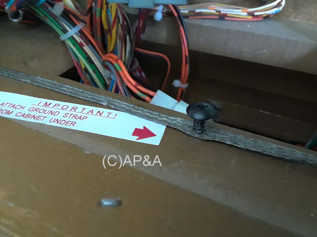
1st Image:
Locate the backbox ground braid screw on the bottom panel of the backbox interior, just in front of the "neck" opening that goes down into the main cabinet. It will be partially installed through the backbox ground braid. Using a Phillips-head screwdriver, remove this screw and set it aside.
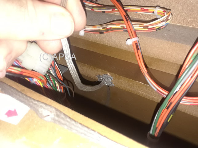
2nd Image:
Locate the cabinet ground braid inside the "neck" of the backbox. It is secured with a screw to the back/center of the top of the backbox opening, just a few inches down from the bottom of the backbox. The other end of the cabinet ground braid will be free and unattached.
Note that some games may have a different location/source for this ground braid coming up from the main cabinet, so you may have to search around for it if you don't see it as pictured here.
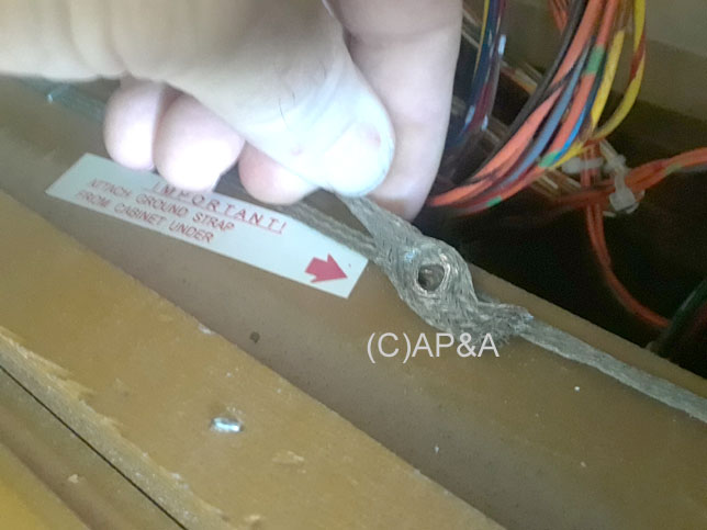
3rd Image:
Gently pull the unattached end of the cabinet ground braid up through the neck, and place it over the hole for the screw you just removed.
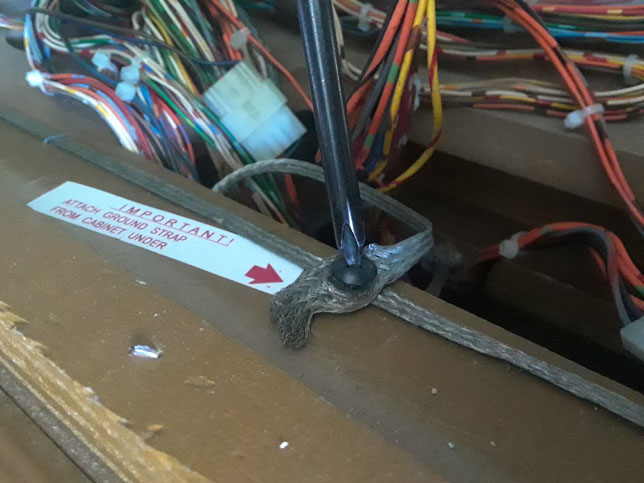
4th Image:
Install the screw through both ground braids and into the screw hole firmly to secure the braids together.
|
 |
Step 11:
Remove playfield glass lockdown bar:
Locate the keys that were shipped with your game's accessories and use them to open the coin door on the front of the game.
1st Image:
Locate the playfield glass lockdown bar release lever, just inside the upper right corner of the coin door opening.
2nd Image:
Pull lever to the left to release the playfield glass lockdown bar.
3rd Image:
Lift the lockdown bar up to remove it, and set it aside.
|
 |
Step 12:
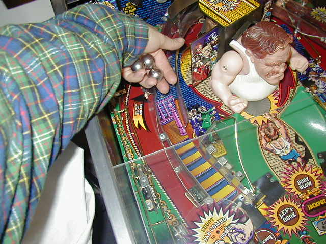
Locate pin ball(s) included in your game's parts/accessories.
Number of balls required will vary from game to game. Here is a listing of quantity used for the games addressed in this article:
- Centaur II: 6 balls (5 in play, 1 captive ball installed in upper left lane on playfield)
- Eight Ball Deluxe Limited Edition: 1 ball
- Mr. & Mrs. Pac-Man: 1 ball
- Rapid Fire: 55 balls (5/8-inch diameter)
Pull playfield glass down a short distance and place the pin ball(s) on the playfield surface and let them roll down to the outhole.
Slide playfield glass back up. Make sure the lockdown bar release lever is still in the left position, and replace the lockdown bar. Then lock the bar in place by sliding the release lever back to the right position. You may need to press down on the lockdown bar to make this step easier. Lever must go all the way to the right in order for the coin door to close. Close and lock coin door. |
 |
Step 13:
Power up:
Plug line cord (located on back of machine) into a grounded outlet.
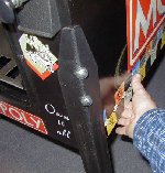
Turn game on by the main power switch. This switch is located under the front right corner of the main cabinet (behind front right leg) on the bottom side of the main cabinet (see picture). It is in a recessed hole on the underside of cabinet. Flip switch to the ON position, and verify that the game lights up, indicating power is present.
Bally games will take approximately 10 seconds to perform a self-test and fully boot up, at which time the score displays will illuminate, lights will flash on/off, and the game will emit a sound effect indicating successful boot-up.
|
You are now ready to play!
Game Levelling:
You may need to level the game from side to side, depending on how the leg levelers are set on the legs, or on the evenness, or un-evenness of your floor. You can "eyeball" the game for level from side to side, or use a bubble level, in two positions- across the front of the playfield glass, and across the back of the playfield glass. Adjusting the leg levellers on the legs will allow the game to be properly levelled.
If you notice the ball rolling more to one side than the other during play, you may need to adjust the leg levellers to re-level the game.
Raising the back of the game (by adjusting leg levellers out (or "down"), on the back legs) will make the angle of the playfield steeper, and cause the ball to roll faster, and game play to be more difficult.
Lowering the back of the game (by adjusting leg levellers in (or "up"), on the back legs) will make the angle of the playfield less steep, and cause the ball to roll slower, and game play to be easier.
You may want to get someone to help lift one corner of the game up slightly while you adjust each leg leveller.
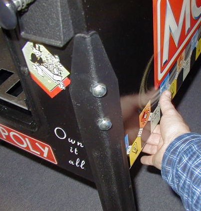
Game Keys:
Your game will have two keys, or two sets of keys- one for the coin door, and one for the backbox. Some games will use the same key for coin door, and backbox. The key(s) for the backbox can be stored on a hook on the inside of the main cabinet. On Bally games from the early 1980's, a key hook is present on the inside of the cabinet, behind the left front leg (see image below).
Keys for your game should be kept in a safe place. No one should need to get into the machine for any reason other than for maintenance/service, etc. And high voltage is present inside the game (even when game is turned off), so best to keep coin door locked and keys in a safe remote place to keep unwanted hands and fingers out of the machine.
Don't hide your keys too well! The number 1 problem we see on local repair calls is lost keys.
Game Manual:
A game operation/instruction manual is included with your game, and ships in a manilla envelope. Please keep this manual in the envelope, inside your game, so it does not get lost (the number 2 problem we see on local repair calls (after lost keys) is lost manuals).
The best place to store the manual/envelope in Bally games is just behind the coin box area inside the main cabinet (there is a clear empty space here between coin box area and power supply where the manual/envelope can be stored).
Other Information:
Consult the game manual that was included with your machine for additional information on game operation, how to make adjustments to game settings, options, or volume, etc. And of course, if you have any questions that you cannot find answers for, just contact us.
Score Display Panel Access:
Access to the score display panel on short-backbox Bally games is not included in the game manual, so we have included some steps/pictures here for your reference.
The score display panel normally does not need to be accessed, so we recommend using this information only if the score displays require service. Please note that extremely high voltages are present on the score displays, so never access them with the power on (and always wait 60 seconds after turning off power before accessing them).
|
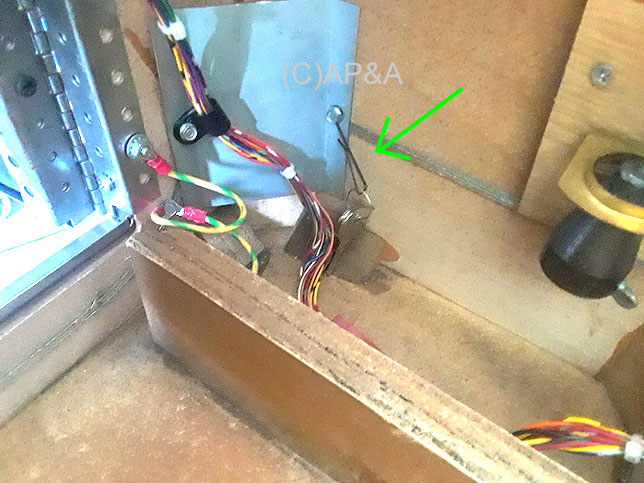
Step 1:
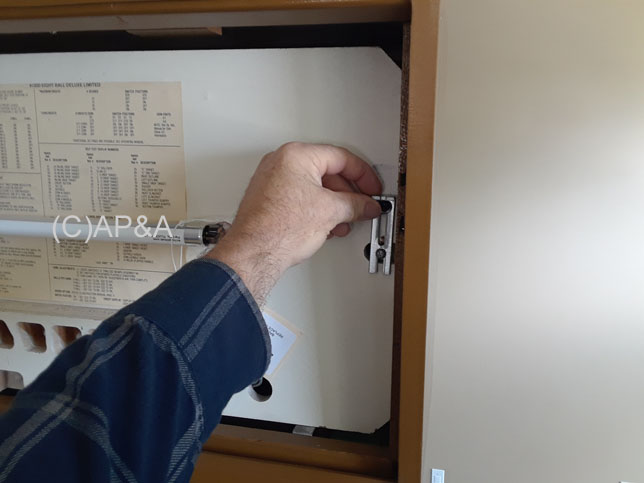
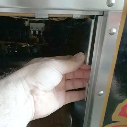
Unplug game to remove electrical power. Open the backbox and locate the 2 sliding metal latches down in the "neck" area between the backbox and main cabinet. Left latch shown (right latch similar- not pictured).
When the latches are in the forward position (as pictured), they keep the Plexiglas cover in place over the displays so that it cannot be lifted up and removed.
Slide each of the latches back as far as they will go (about 1/2 inch each). Sometimes they are a bit stubborn on some games, so you may need a flat blade screwdriver or pair of pliers to help (use caution not to contact or damage any wiring or electronics in the backbox).
|
|
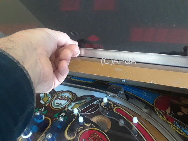
Step 2:
Use the metal lift channel at the bottom of the display cover to lift the cover up, as it sits in the backbox frame. The cover should lift up about 1/2 inch, and clear the bottom of the backbox frame.
Tolerances are very tight on the parts for the score display panel and cover, so you may need to lift up firmly on both ends of the cover, and maybe even wiggle it a bit, to get it to clear the bottom of the frame.
|
|
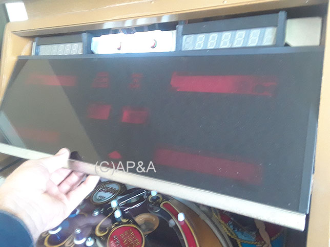
Step 3:
Pull the bottom of the cover out so it clears the frame, and then lower it down to fully remove it from the backbox.
Carefully set it aside.
|
|
Step 4:
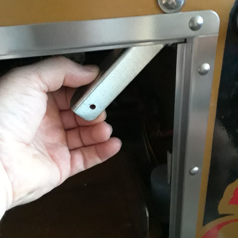
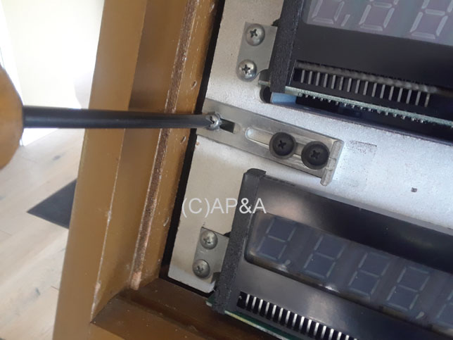
Locate the 2 horizontal sliding latches on either side of the score display panel (left latch shown- right latch similar). Both are secured by a SEMS screw. Use a Phillips-head screwdriver to remove both screws from the 2 latches.
Normally, you would just loosen the SEMS screws, then slide the latches inward to relase the panel, but the way Bally designed these games, this usually doesn't work, due to the tight tolerances of the parts in the score display panel area. So we recommend removing the 2 SEMS screws completely.
|
|
Step 5:
With the latch SEMS screws removed, the score display panel will be loose, and can be removed.
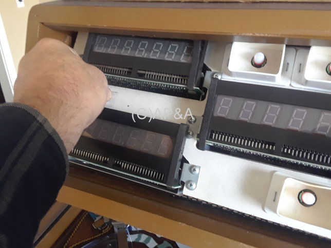
1st Image:
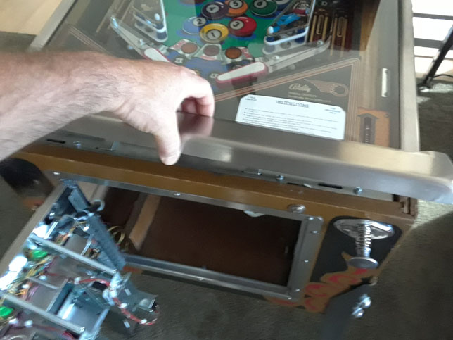
Bally didn't design a convenient way to do this, so we recommend using the 2 latches as tabs/handles to help hold the panel as you remove/install it. Be careful not to use the displays, the metal display trays, or the white plastic shrouds around light bulbs as handles, as these are all delicate parts and can be easily broken or bent.
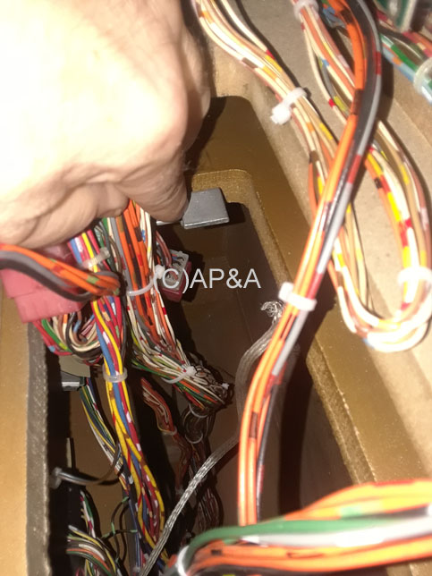
The easiest way to remove the loose display panel is to lift it slightly up, while tilting the top edge inward into the backbox, as shown in 1st image. Then continue to rotate the top into the backbox as you pull the lower part out. Then let the top follow.
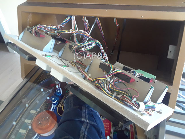
2nd Image:
With the panel free of the backbox, you can lay it down onto the playfield glass for access/service. A 24-pin cable that comes off the panel between the 1st and 3rd play displays has a connector on it about a foot up into the backbox. You can unplug this connector to allow the panel to be fully removed from the game.
|
Reverse the above steps to re-install the display panel. Panel can be adjusted slightly up/down for alignment with the Plexiglas cover by raising the panel and then tightening the 2 SEMS screws accordingly.
If you have any questions, problems, or require any additional information, please contact us.
Back to Top
|

 Game Setup & Assembly Information